To know more about the different arguments of these functions, and to know about the other important functions related to Wire, you can check the Arduino reference on Wire. Alternatively, if master transmitted bytes to a slave, this function on the slave will be used to read the bytes Wire.read() − If a master send requestFrom() to slave, then it will read the returned byte using this function. (1, PIOSERCOM) //Assign SCL function to pin 1 myWire.
#Wire library assign scl pin how to
Wire Slave Sender on pins 0 and 1 on MKR1000 Demonstrates use of the Wire library and how to instantiate another Wire Sends data as an I2C/TWI slave device Refer to the 'Wire Master Reader' example for use with this. Wire.write(byte) − Queue bytes for transmission from master to slave, or write data from slave in response to request from master SCL on pin 12 UART / SERCOM 5: RX on pin 13. Wire.SetClock(frequency) − Set the clock speed to frequency (in Hz) Wire.endTransmission() − End a transmission initiated by beginTransmission()

Wire.beginTransmission(address) − Initiate transmission with the slave identified by address The important functions of this library are given below −

The following pins are generally used for SPI −Īrduino has a built-in Wire library.

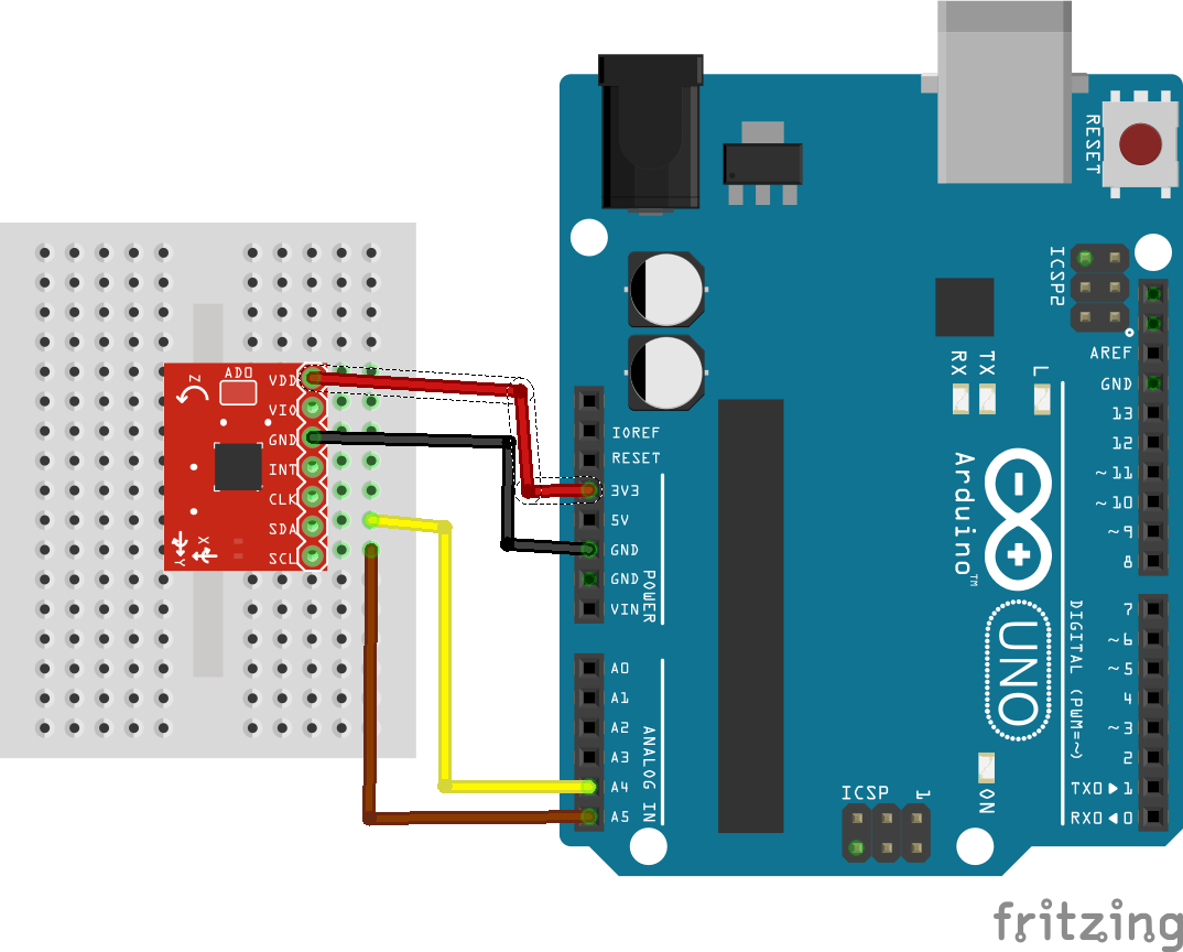
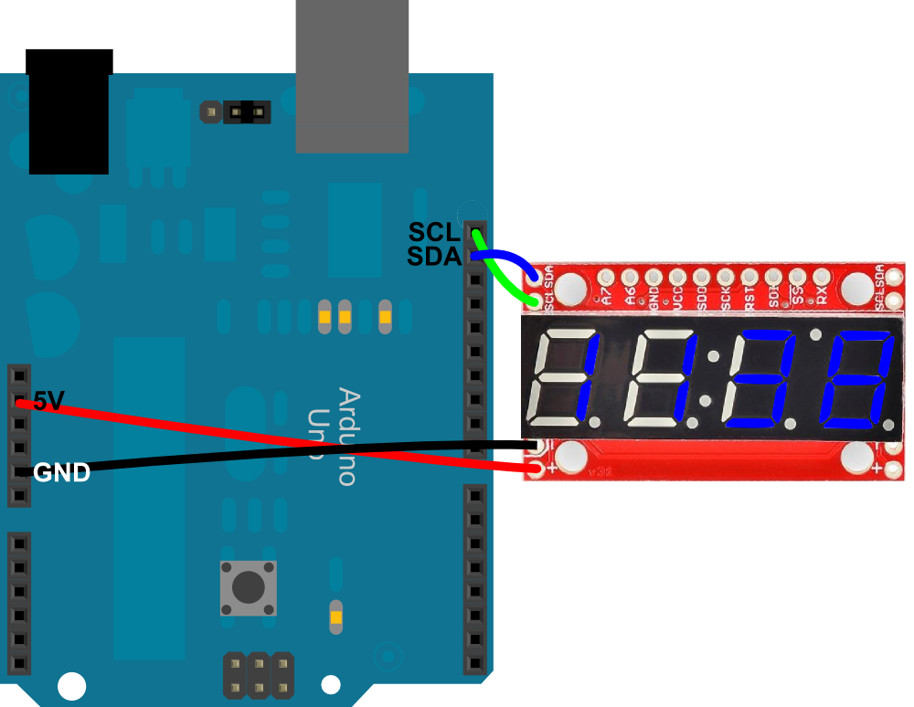
Start/Stop sequence is required to signal start and end of communication If they want to send high level, they simply release the bus. two resistors pull the bus to a high level and the devices only send low levels. The data and clock lines are pulled up, i.e. The slave has to make sure that the next bit is ready when the clock pulse arrives If the master wants to receive the data, it only generates clock pulses. Thus a maximum of 127 slaves with unique addresses can be connected to a single master.Īfter each byte, the receiver must send a 0 to acknowledge the reception of the byte The first byte sent by the master contains a seven-bit address and a read/ write bit indicating whether the next bytes will come from the master or should come from the slave. The slaves are not selected via a slave select line, but via address bits. I2C is synchronous because it uses a clock. So connect it to 5V I wasn't able to make it work as shown in the diagram however if I removed the point where the sda and scl line are connected to +5v via 4.7ohm resistor it work fine BTY GrumpyMike midifoot controller also supplies those line with. It uses only two lines: One for data (SDA) and one for clock (SCL). Pin 18 is the reset pin, which is normally high therefore you ground it to reset the IC. Arduino refers to I2C as Wire, which is a shorter form of the term Atmel uses (Two Wire Interface or TWI). It is a popular communication protocol used by several peripherals like accelerometer and gyroscopes, OLED Displays, etc. When the clock pin changes from high to low (the falling edge of the clock), the called upon device transmits it's data back to the Arduino over the same line.īecause the 12C protocol allows for each enabled device to have it's own unique address, and as both master and slave devices to take turns communicating over a single line, it is possible for your Arduino to communicate (in turn) with many devices, or other Arduinos, while using just two pins of your microcontroller.I2C stands for Inter-Integrated Circuit.

As the clock pulse changes from low to high (known as the rising edge of the clock), a bit of information containing the address of a specific device and a request for data, is transferred from the Arduino to the I2C devices over the SDA line.
#Wire library assign scl pin serial
The I2C protocol involves using two wires to send and receive data: a serial clock pin (SCL) that the Arduino pulses at a regular interval, and a serial data pin (SDA) over which data is sent between the two devices. Once that message is received, it can then be viewed in the Arduino serial window. Arduino 1, the Master, is programmed to request, and then read, 6 bytes of data sent from the uniquely addressed Slave Arduino. Several functions of Arduino's Wire Library are used to accomplish this. In this example, two Arduinos are programmed to communicate with one another in a Master Reader/Slave Sender configuration via the I2C synchronous serial protocol. GPIO 22 (SCL) If you want to use other pins when using the wire library, you just need to call: Wire.begin(SDA, SCL) Learn more about I2C communication protocol with the ESP32 using Arduino IDE: ESP32 I2C Communication (Set Pins, Multiple Bus Interfaces and Peripherals) SPI. The standard Arduino library cannot be used for I2C on the Attiny because it does a call to. The LiquidCrystalI2C library works in combination with the Wire.h library which. It needs the TinyWireM library to act as an I2C master. If you are not using an Arduino Uno, the SDA and SCL pins can be at a. The 'Wire' library that is used to read and write bytes from and to the I2C port on the arduino doesnt work on the attiny. In some situations, it can be helpful to set up two (or more!) Arduino boards to share information with each other. The attiny85 can simulate I2C on PB2 (pin 7) (SCL) and PB0 (pin 5) (SDA). Learning Examples | Foundations | Hacking | Links


 0 kommentar(er)
